Basic Welding Symbols On Drawings Images and Photos finder
Fig. 1. Fig. 2. Fig. 3. Fig. 4. Symbol types To the basic set-up of the arrow and reference line, the design draughtsperson can apply the appropriate symbol, or symbols for more complex situations. The symbols, in particular for arc and gas welding, are often shown as cross-sectional representations of either a joint design or a completed weld.
Welding Inspection
You don't often see "weld here" on a blueprint. This is because it's too vague and can mean different things to different people. Welding involves more than just where to weld; it also involves how to weld, what type of weld to use, and so on. Just saying "weld here" can lead to confusion and mistakes. Advantages of Welding Symbols
Easy Guide to Welding Symbols
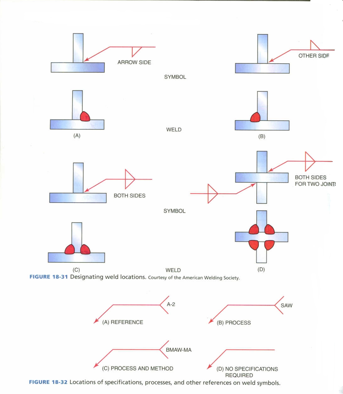
Sometimes drawings are very full, so this rule is necessary in case there is no room for the base symbol to be on the side the weld is. Base system B Here, when the welding symbol is on the underside of the reference line, the weld is on the side the arrow points at.

Free Symbol blockswelding symbols Free Autocad Blocks & Drawings Download Center
International standard for welding symbols now updated 2 minutes to read Clare Naden 6 January 2020 Welding symbols are a necessary element of engineering, providing a common language for all involved in fabrication, from designers to the shop floor. The internationally agreed standard for these symbols has been updated.
Welding Terms and Symbols Basic welding symbols Engineersfield
Welding Symbols are a graphical way to convey information about a welding joint. Instead of using an arrow and saying 'weld here', a weld symbol carries more useful information that can be easily understood by the welder, engineer, foreman, supervisor and architect.
Welding Symbol Engineer Diary
Locating Butt/Groove Weld Symbols; The placement of butt/groove weld symbols on engineering drawings follows specific conventions. The symbol is positioned above the reference line, and its arrow points to the joint's location. Proper alignment and measurement are crucial to accurately conveying the weld's position and dimensions. Fillet Welds
Understanding the Welding Symbols in Engineering Drawings Safe Work Method Of Statement
6 Common welding symbols. 1. Arrowhead and reference line. This allows you to quickly identify that you are looking at a weld symbol. The arrow points at the joint where the weld will be placed, while information about the orientation and type of weld will be included along the arrow side, or reference line.
Welding Symbol Application on fabrication Drawing PART 2 YouTube
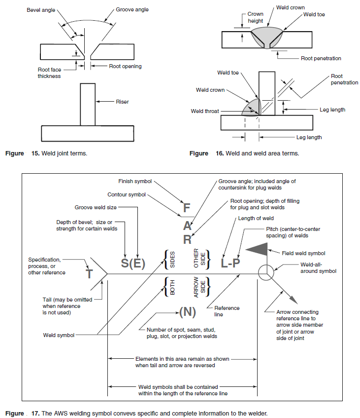
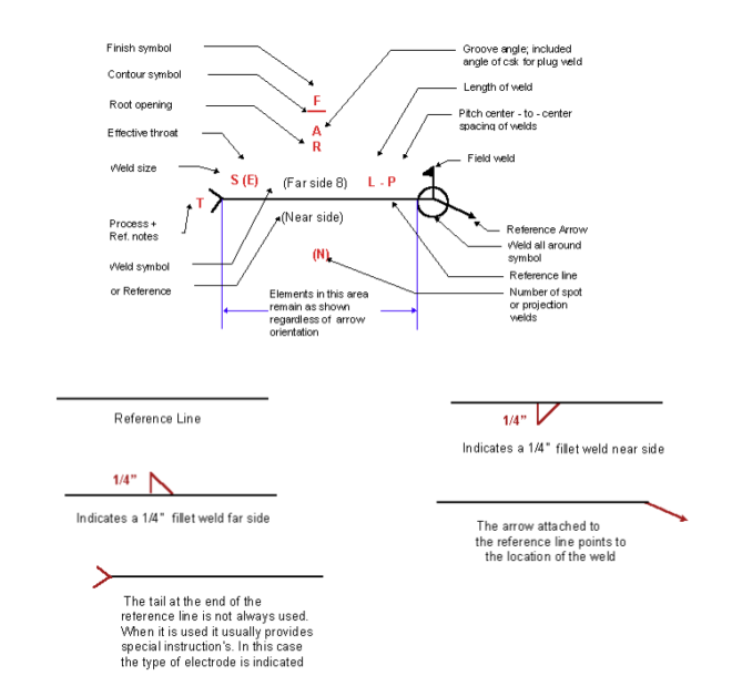
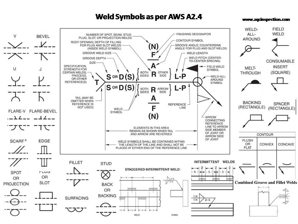
American National Standards Institute (ANSI) and the American Welding Society (AWS) publish ANSI/AWS A2.4, Symbols for Welding and Nondestructive Testing, which provides a complete set of symbols. The structure of the welding symbol The horizontal line — called the reference line — is the anchor for all welding symbols.

Terms Used With Welding Symbols Welding projects, Welding table, Welding
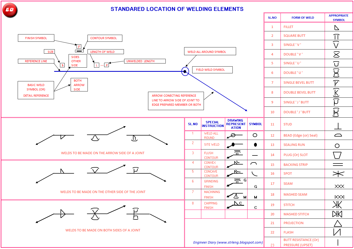
Welding Symbols 3-1. GENERAL 3-2. PARTS OF A DRAWING 3-3. CONSTRUCTION LINES 3-4. GENERAL 3-5. ELEMENTS OF A WELDING SYMBOL 3-6. BASIC WELD SYMBOLS 3-7. LOCATION SIGNIFICANCE OF ARROW 3-8. LOCATION OF THE WELD WITH RESPECT TO JOINT 3-9. REFERENCES AND GENERAL NOTES 3-10.

Weld Symbols
34206-11 Welding Symbols TG Nccer,2011-01-15 Explains the different parts of a welding symbol and how to read symbols on welding drawings, specifications, and welding procedure specifications. Describes the symbols for fillet welds, groove welds, miscellaneous other welds, and non-destructive tests. Welded, Brazed and Soldered Joints.
Aws Welding Symbols On Drawings My XXX Hot Girl
1. Scope This standard outlines the method of presenting welding symbols. It is applicable to both metal fusion welding and resistance welding. 2. Normative References GB/T 5185 Designation of Metal Welding and Brazing Methods in Drawings; GB/T 12212 Technical Drawings - Dimension, Proportions, and Simplified Representation of Welding Symbols. 3.

Luxury Welding Symbols On Drawings Welding, Symbols, Welding tips
The weld symbols are always placed on the reference line of the welding symbol. A welding symbol is what you see on the fabrication drawing. It communicates the location of welding, the type of welding, and all the other details required by the fabricator to execute the fabrication. A welding symbol uses ' weld symbols ' to convey the type.
Welding Symbols Chart An Explanation of the Basics (with Pictures) WaterWelders
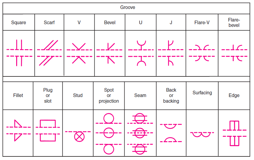
It usually involves preparing the edge pieces to form one of the groove weld shapes like V, bevel, U, J, Flare V, Flare bevel or no preparation at all with square edges to form a square groove. Plug/slot - These are welds used to form overlapping joints using holes in which welds get deposited. Flange or edge welds.
Iso Weld Symbols Chart
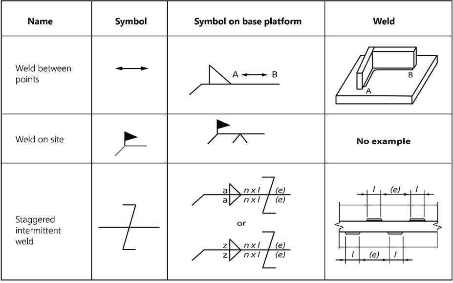
A dashed line A symbol Note: Weld symbols on the full reference line relates to welds on the near side of the plate being welded. Weld symbols on the dashed line relates to weld on the far side of the plate. If the welds are symmetrical on both sides of the plate the dashed line is omitted.
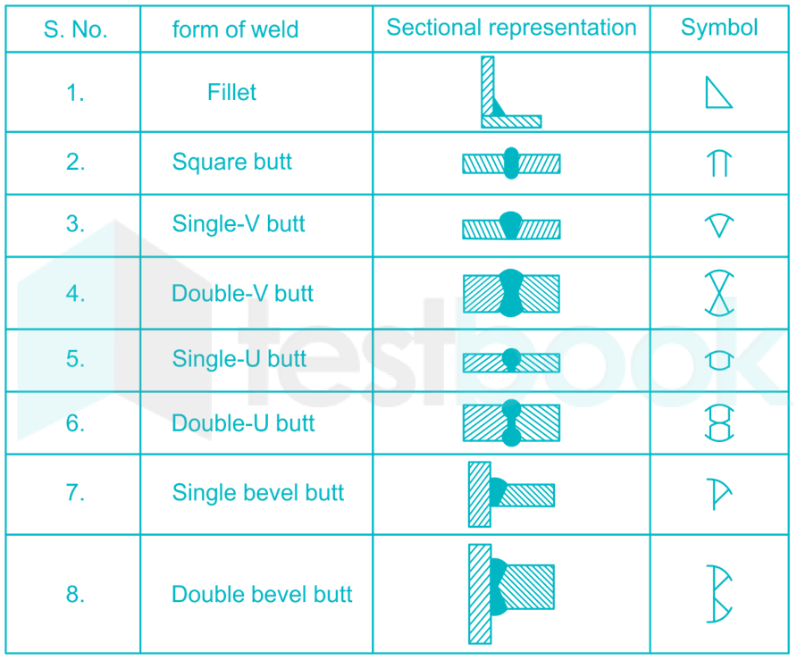
[Solved] In engineering drawing, the welding symbol used for fillet w
The weld symbol specifies the type of weld to be applied to a part. The welding symbol is made of several parts including the reference line, arrow, and weld symbol when required. The symbols in this book are a representation of what weld and welding symbols look like. There are specific design requirements when used in accordance to a blueprint.

Drawing and Welding Symbol Interpretation Welding Class Welding table, Welding projects
Reference line, Arrow Line, and the Tail. The reference line is a horizontal line that is used to align the other elements of the symbol. The arrow is used to point to the location of the weld, and the tail contains information about the type of weld, size, and other details.
